Car chasing games can be an exciting and immersive way to spend your time. Not only do they offer a thrilling experience, but they also give you the opportunity to sharpen up your driving skills and reflexes in a safe environment. It is important to remember that car-chasing games like Drift Hunters are just for entertainment and should not be taken as a substitute for real-life driving lessons or practice on open roads.
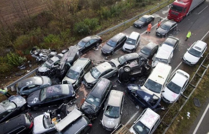
Unfortunately, road accidents are an everyday occurrence. They can happen to anyone for whatever reason. But, after reading the car accidents related facts, we have listed below, you will probably become a safer driver, and be less prone to putting yourself and others in danger while on the road. Our list contains 20 facts, and the scariest one is that four road accidents will happen while you get to the end.
1. On a yearly level, road accidents kill more than 130,000 people in the US, meaning that this is the fourth most lethal killer in America. Only heart diseases, cancers, and respiratory diseases kill more.
2. The vast majority of road accidents that happens to people occur in the 3-kilometer radius of their home.
3. According to the U.S. Department of Transportation men are more likely to have motor vehicle accident than women. This happens because women avoid risky driving and are more likely to wear a seat-belt.
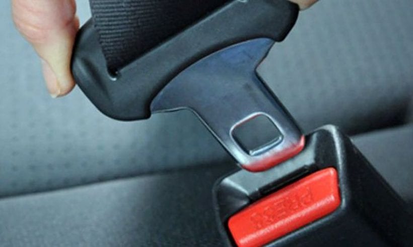
4. By wearing a seat belt, you are reducing the chances of death in a case of a car accident by 50%. Like we said women are 10% more likely to have a belt on than men.
5. If you reduce your average speed on the road by 1km/h, you are 2% less likely to have a car crash.
6. Since enforcement of rigorous measures for drinking and driving began around the world road accidents related to this issue were reduced by 20%.
7. Bike riders who wear helmets reduce the chances of having a fatal head injury by 45%.
8. The main thing with wearing a seat belt is to do it correctly. If you fasten your seat-belt correctly, you reduce the risk of death by 61%.
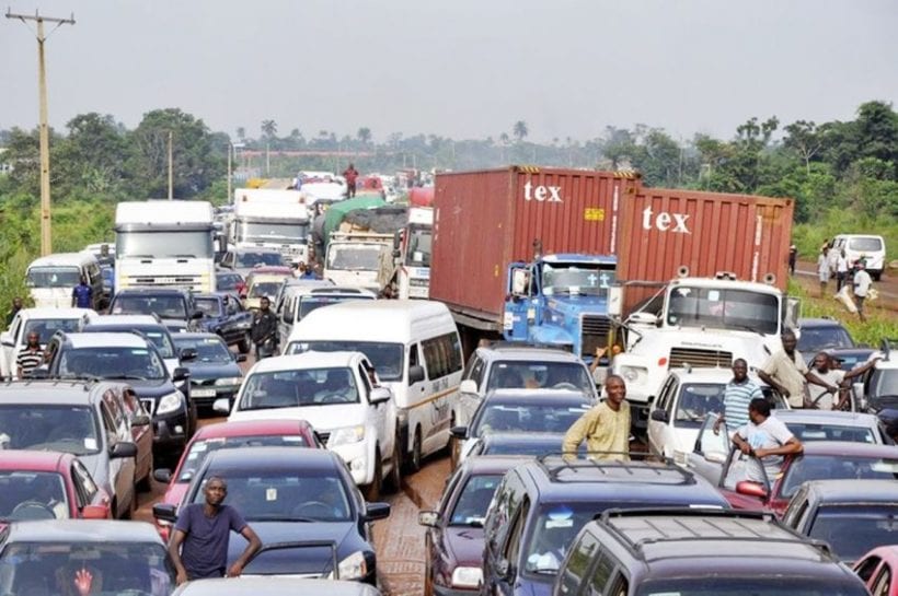
9. Most road accidents are caused by distractions, fatigue, environmental conditions and medical or emotional impairment.

10. On the world level, during one year period, more than 1.3 million people die in car accidents.
11. 50% of all fatal crashes that involve motor vehicles are DUI related.
12. On a yearly level, 4,387 pedestrians are killed by motor vehicles on the roads and highways in the United States.
13. In all 50 states in America, there are laws that are related to seat belts.
14. Fifty percent of all people involved in accidents on the roads are either pedestrians or cyclists and motorcyclist.
15. During a one year span, more than 50 million people get injured in road accidents.
16. Most accidents happen because people neglect the rules. The easiest way to avoid any sort of misfortune is to follow the law, pay close attention to the road, and merely follow the rules.
17. The most fatal crashes occur on weekends between midnight, and 3 am, and it is more likely for drivers to be driving under the influence than in accidents that happen during the week.
18. School buses kill close to 14 school kids every year.
19. The country that has twice as high average death tool related to car accidents compared to the rest of the world is South Africa.
20. The most dangerous group of drivers are young men.